For the last couple of months, I’ve been developing an HDMI mod for the Vita on my free time. I thought it would be a fun project to practice my hardware design skills even though the end product would not be too useful (the VitaTV already exists). Unfortunately, this project did not end in success but I want to write about it anyways so you can see what I’ve been doing with some of the leftover money from my adapter project.
Overview
The Vita’s SoC (named Kermit) has two MIPI DSI output ports. On OLED units, the first port is connected to a custom 40-pin high speed board-to-board connector that mates with an AMS495QA01 OLED panel. On LCD units, the same port goes to a ZIF connector. The second port is unused on handheld Vitas and is connected to an ADV7533 on the PSTV. On development kits, both ports are used (one to OLED and another to ADV7533) and I suspect that’s why the SoC has two ports in the first place. I would like to comment here that the Kermit SoC does not have native support for HDMI/TMDS signaling and therefore any rumors of handheld Vita consoles having HDMI output capabilities are false. No, that “mystery port” does not have video output capabilities (it is a USB host port with a custom physical connector).
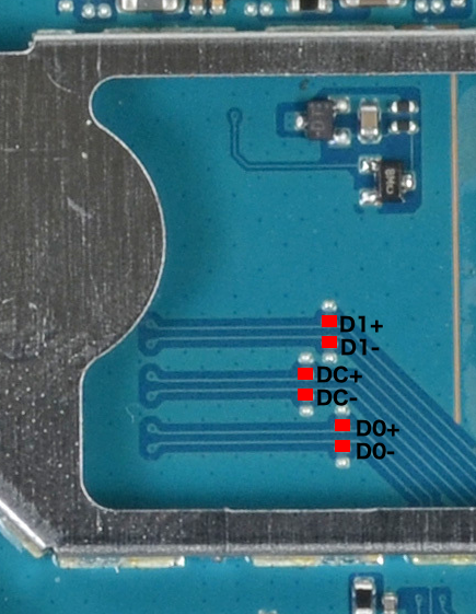
Can we hook up the unused MIPI DSI port? Unfortunately no because those pins are not routed so it is impossible to get to them, so instead the idea is to “hijack” the DSI output to the OLED panel and let the same signals drive a custom board that can convert it to HDMI. This requires us to solder some wires to the video signals and thanks to the OLED datasheet along with some connectivity tests, it was easy to locate test points for the desired signals.
ngptv
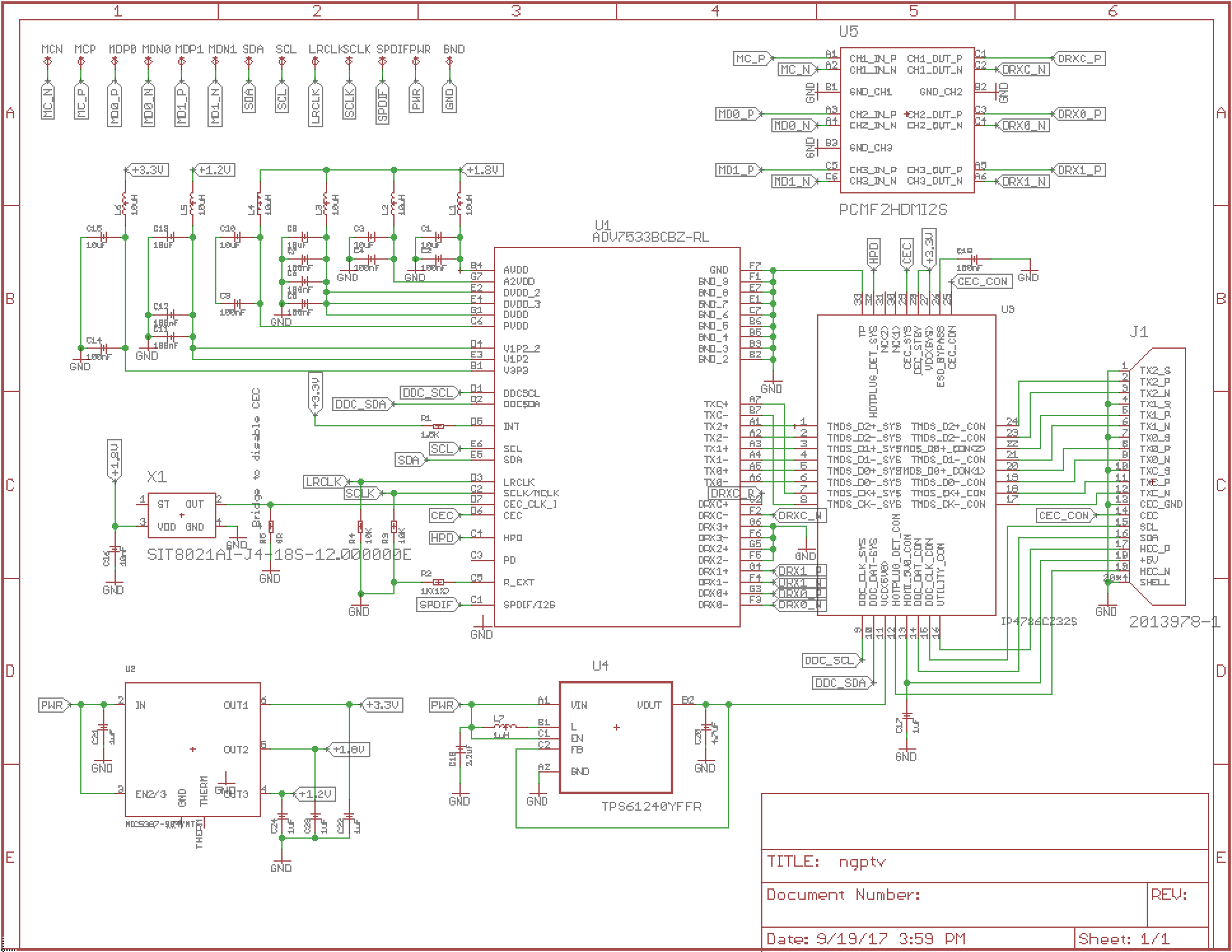
My original idea is to use the same components as the PSTV, namely the ADV7533 MIPI DSI to HDMI conversion chip. It is the only ASIC on the market that does this so there was little choice. Using some other implementation as reference, I drew up a schematic for the board including the recommended circuits to adhere to HDMI standards.
A couple of big problems quickly came up that made this design infeasible
- I wanted to expose a mini-HDMI port on the bottom of the OLED Vita right next to the multi-connector. There is unused space inside the Vita near that region but it is only about 15mm x 15mm. That means all the components I choose will have to be extremely space efficient and therefore expensive.
- The ADV7533 only comes in a 49-BGA package which means layout requires at least a 6 layer board with low pitch and drill sizes. This means that prototyping the boards will be very expensive. A normal 2 layer PCB with standard drills can be fabricated for about $10 for each prototype run. A 6 layer board with small drill sizes goes for about $300 for each prototype run.
- I do not have the equipment to solder and test small pitch BGA parts which I would have to use to meet the space constraints.
- You cannot buy the ADV7533 from standard US suppliers because the part is under NDA and requires you to have a HDMI license which costs thousands of dollars per year.
Since I do not plan to produce these boards at a profit, I cannot justify investing the time and money for this design. However, another approach presented itself to me.
ngptv lite
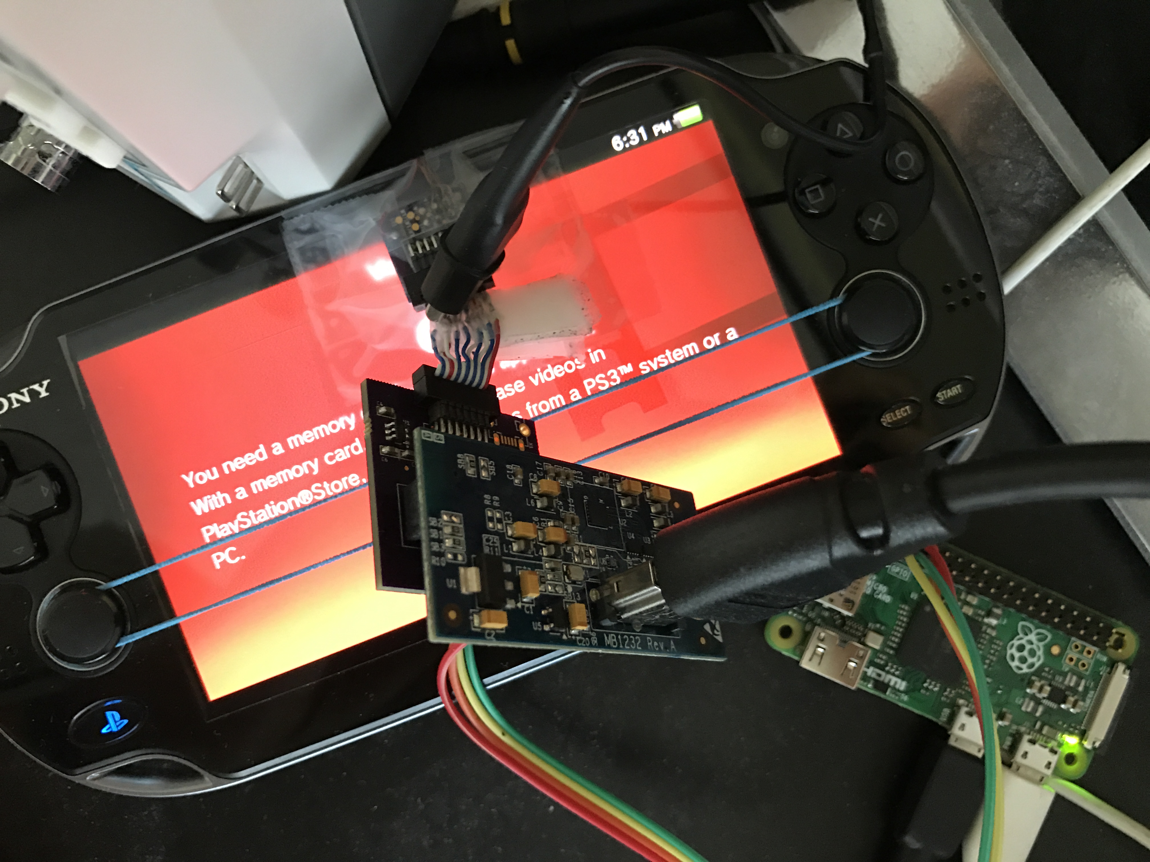
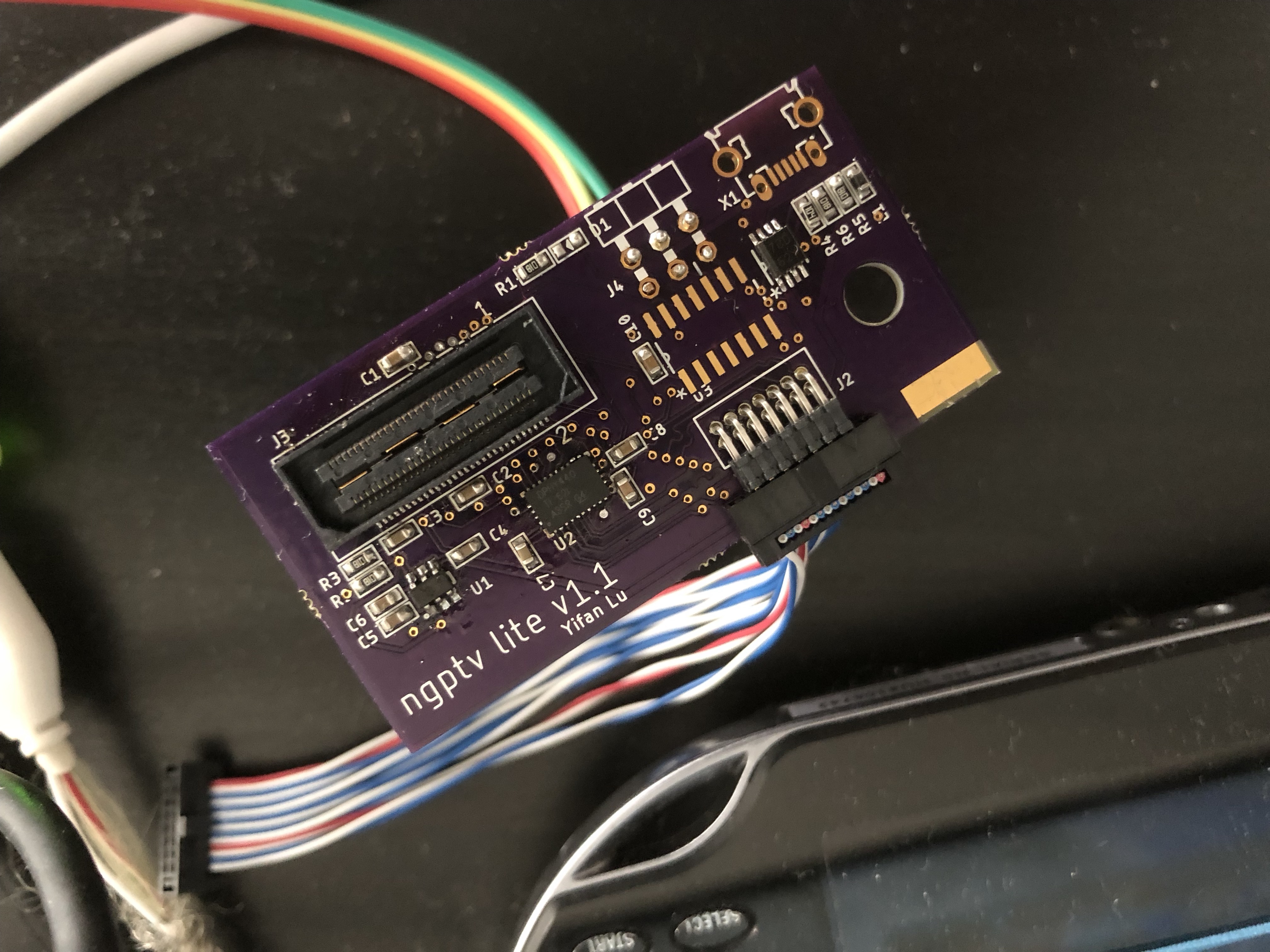
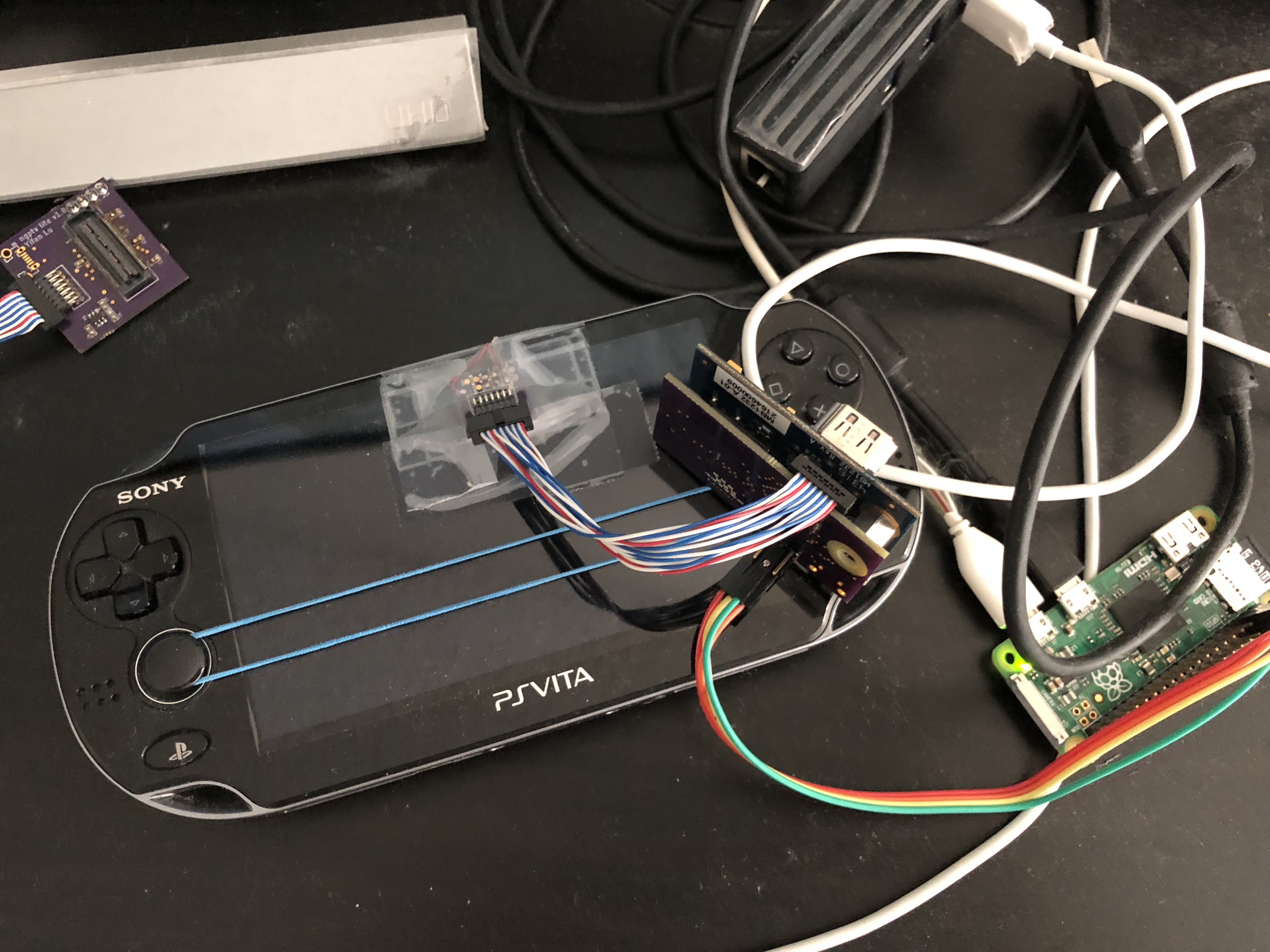
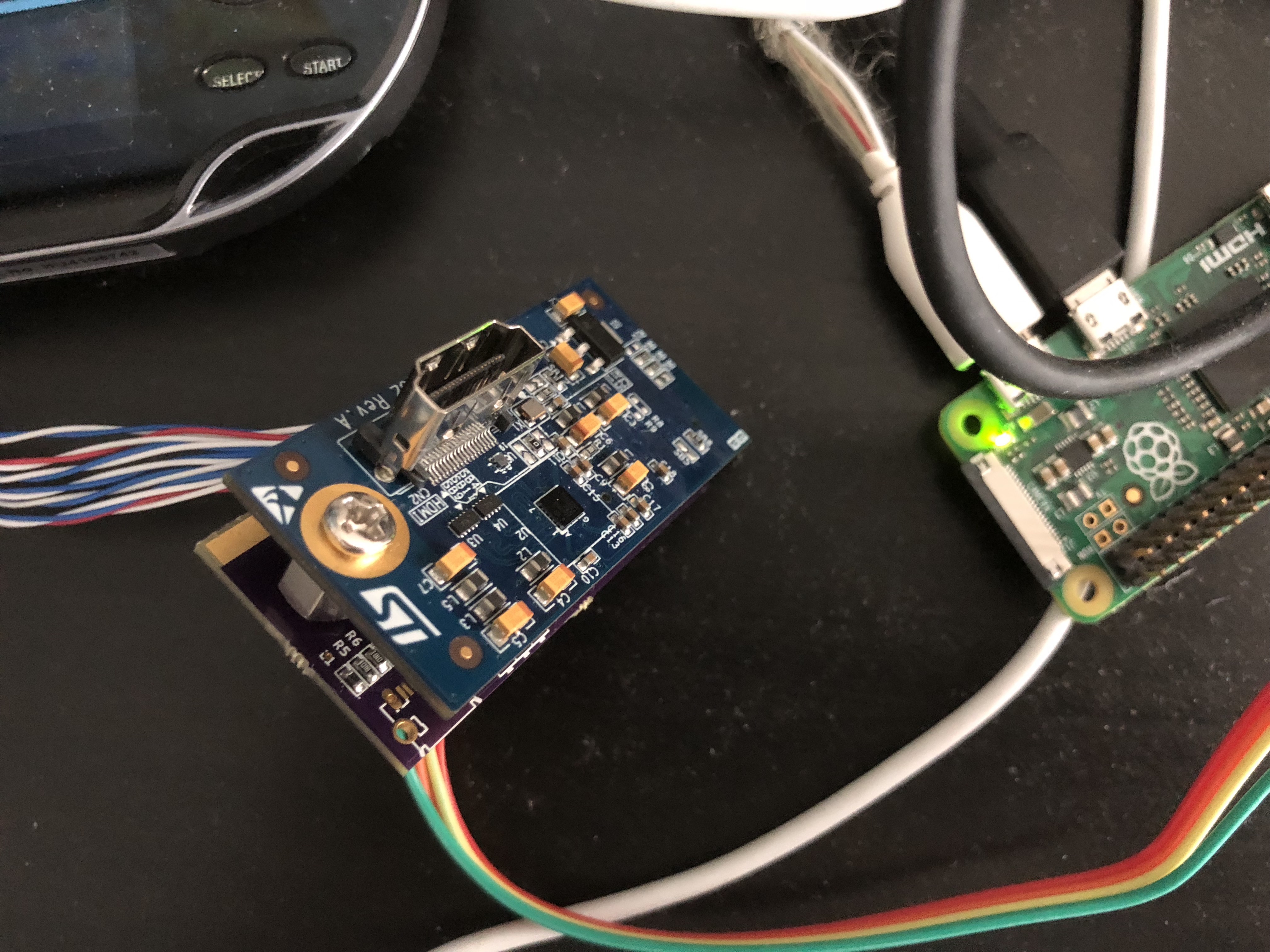
ST makes an adapter board for their MCU evaluation boards (which only has MIPI DSI support) to hook up to external displays. We can easily purchase these for $30 a pop (no license or NDA required) and then build a custom “host” board for it. That’s exactly what I did. I built a small 15mm x 15mm breakout board that can be placed into the Vita and soldered 36AWG wires from the testpoints to the breakout board. Then I built a “host” board that connects to my breakout board and the ST adapter. The host board also has pins to connect to my RaspberryPi so I can power it as well as program the ADV7533. It quickly became a colorful mess of wires.
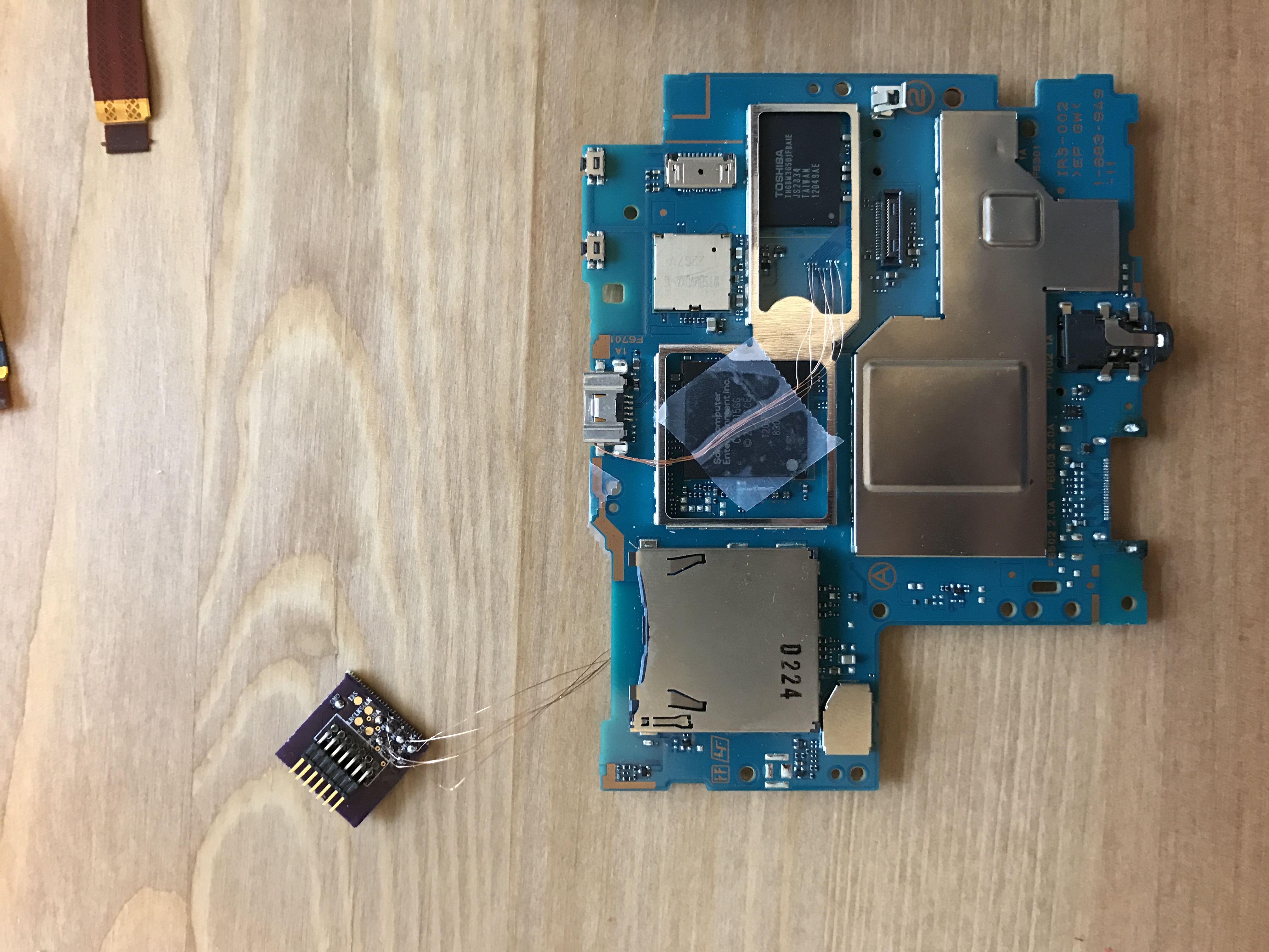
Wiring the breakout board.
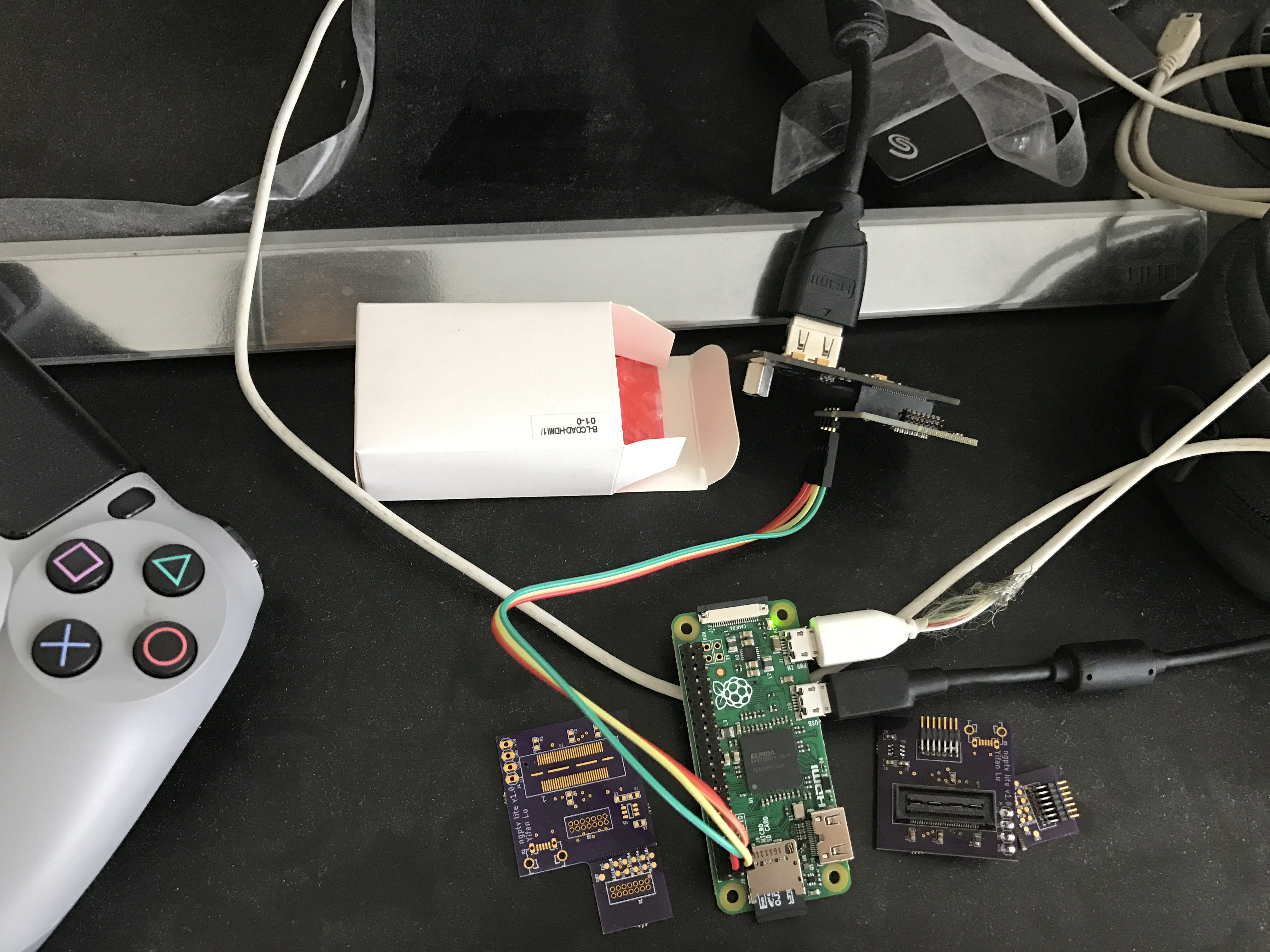
RaspberryPi and what the adapter looks like.
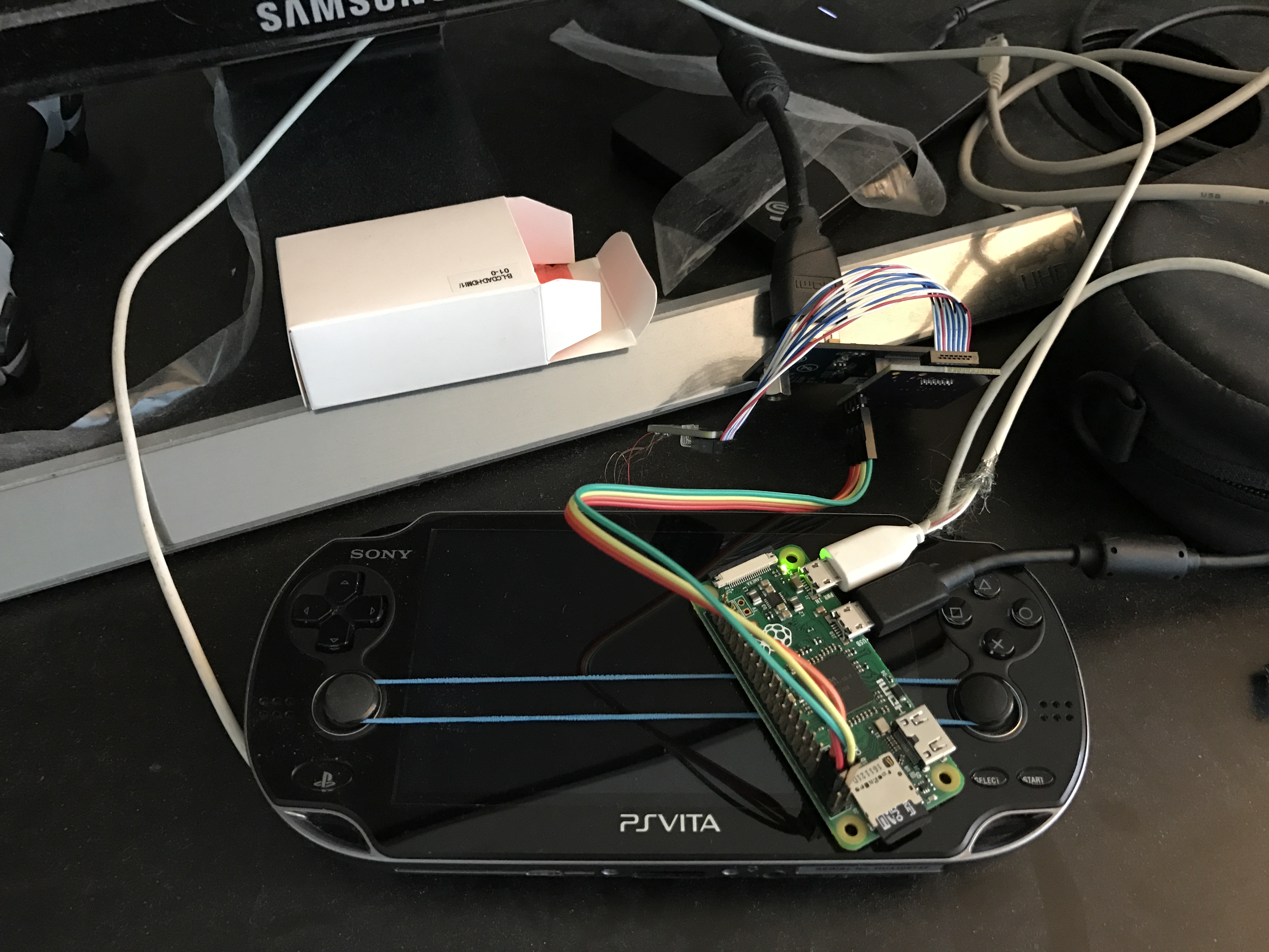
Everything connected together.
Driver
Since the ADV7533 is under NDA, Analog Devices does not give out the programming guide to the public. This makes no sense because there are quite a few open source implementations out there:
- Linux driver
- Marvell Android driver
- Qualcomm Android driver
- ST drivers for evaluation board
- xerpi’s vita-baremetal-sample which uses above
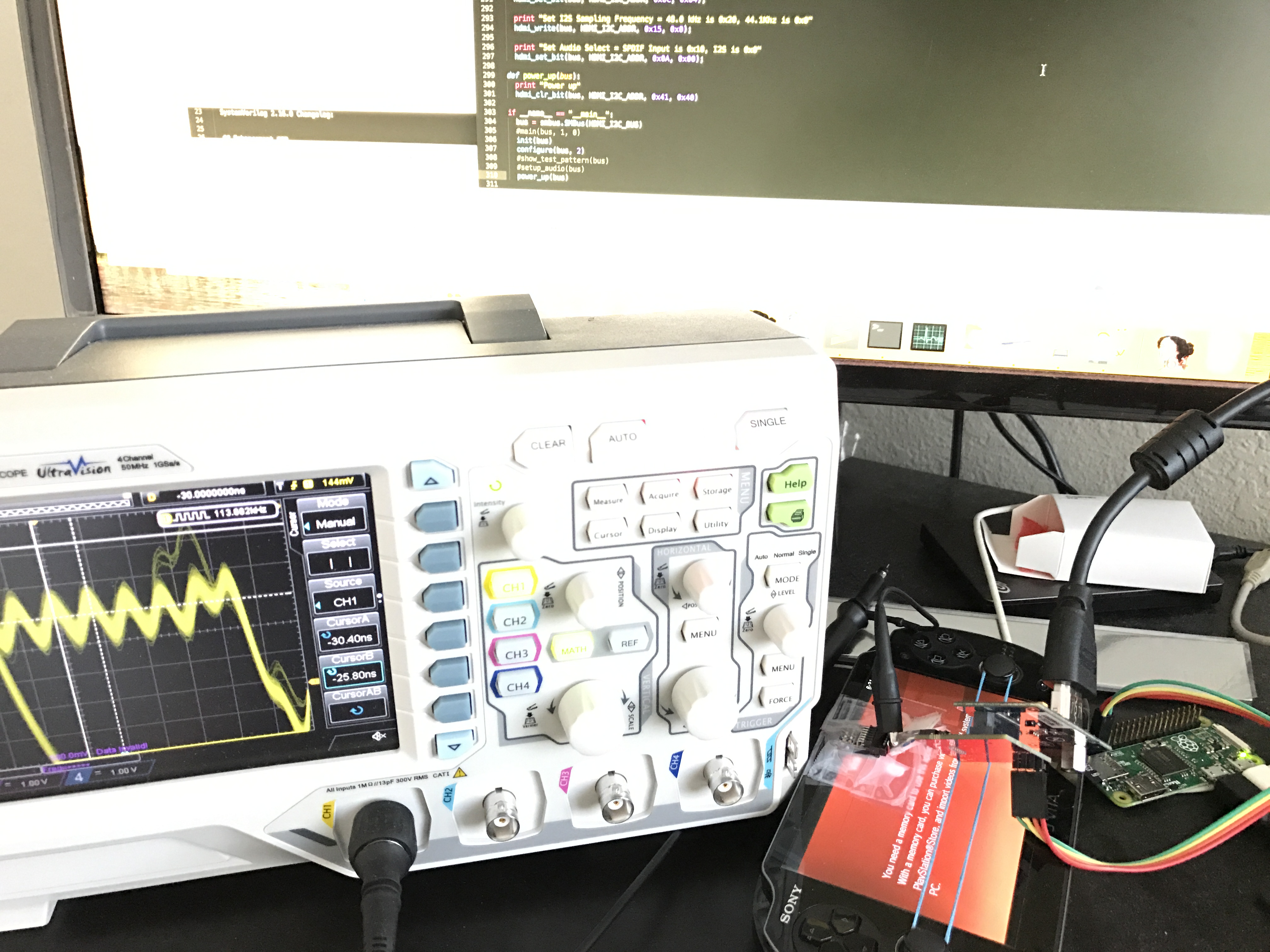
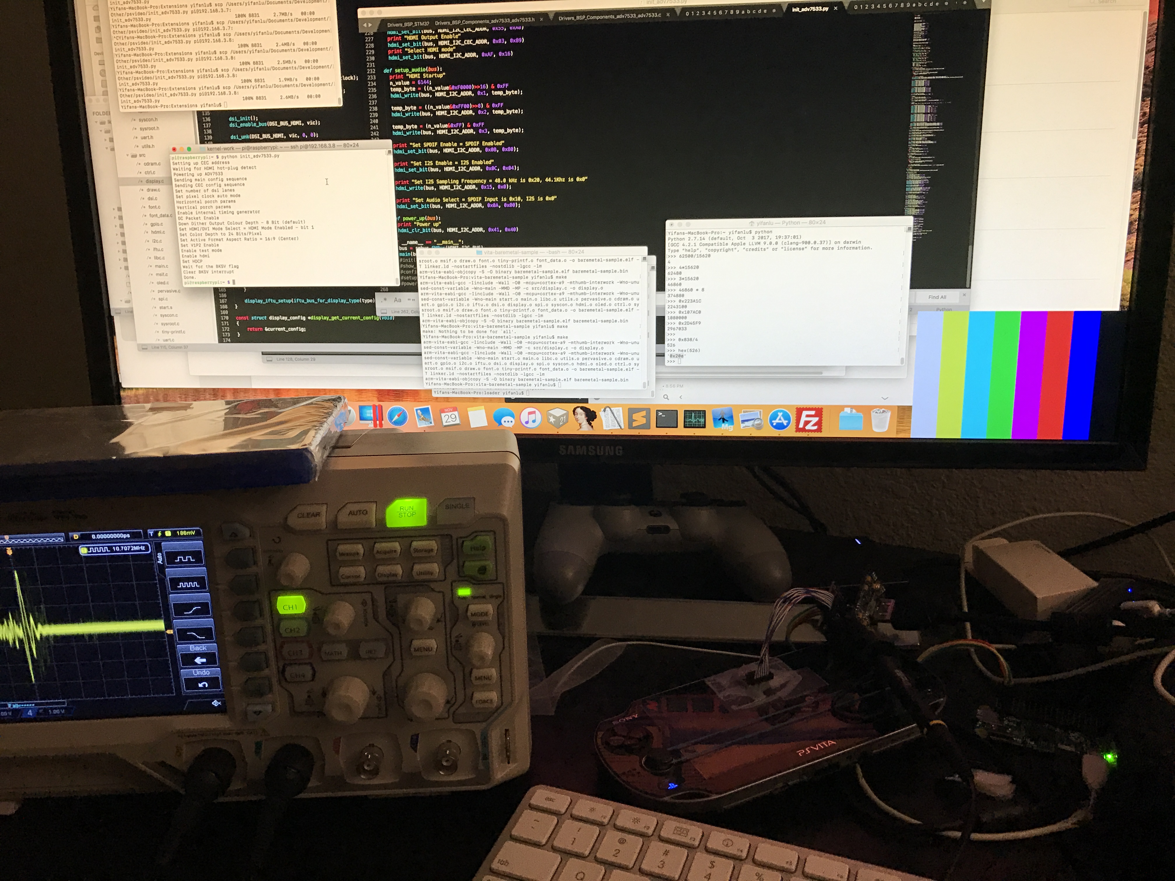
By looking at the different implementations, I was able to piece together the proper configuration flow (as well as find benign bugs and wrong comments in different implementation leading me to believe not all the drivers above were original work). I wrote the I2C configuration sequence as a Python script to run on the RPI, which was able to communicate with the ADV7533 successfully.
However, no video showed up on screen. It’s time to bring out the oscilloscope.
Debugging
After sniffing the clock lanes with my oscilloscope, I’ve noticed something strange: the clock signal is off every 30us.
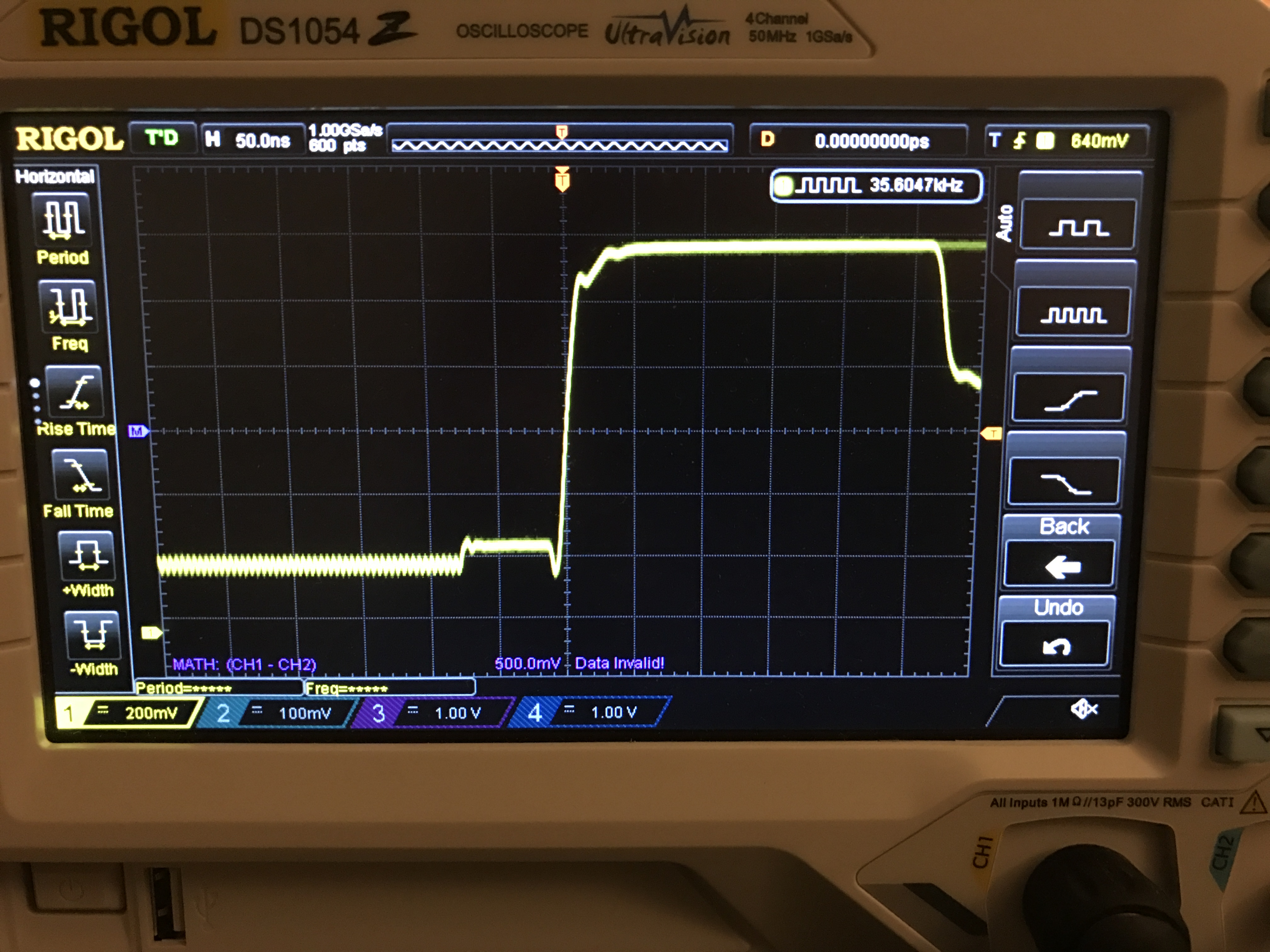
The MIPI D-PHY specifications defines two modes: HS (high-speed) and LP (low-power). In HS mode (also called video mode for MIPI DSI), the clock lanes act as a high speed differential clock while the data lanes transfer the data. This is typically used to send each frame. In LP mode (also called command mode for MIPI DSI), the video source and sink can communicate during v-blank periods and send auxiliary information. The clock lanes are not used when the data lanes are in LP mode and therefore to save battery, the clock lanes can also enter LP mode and is seen as off. Unfortunately, the ADV7533 datasheet states the following on the first page:
The DSI Rx implements DSI video mode operation only.
This implies that there is no logic to handle the clock lane LP transition. To test this hypothesis, I used xerpi’s vita-baremetal to set up the MIPI DSI clock the same way the PSTV does and sure enough I see in my oscilloscope that the clock no longer turns off and I can see test patterns on the screen.
Cursory tests shows that the Vita OLED does not like the clock running continuously so it does not seem possible to have the OLED and HDMI working at the same time. I also don’t want to limit the adapter to only working with hacked Vitas, so I thought to find another way. I tried asking around to see if there is some magical IC that can derive a fixed clock that is phase synced to the pixel clock but stays on. Initially I thought I found a solution with jitter attenuators/cleaners but then I was told by an engineer that a jitter cleaner would average out the clock rather than ignore the “off” periods. It would be way too expensive to build a custom solution using FPGA or op-amps and PLLs that can handle > 250MHz differential signals.
Redesign
Nevertheless, I decided to redesign my host board just to hone my design skills (which is the whole point of the project anyways). I wanted my board to be the same size as the ST board and have the connectors align so they can sit on top of each other. I also added a MIPI DSI redriver with a configurable equalizers. This ensures the video signal going to the ST adapter is clean. Finally, I added a microcontroller so I can program in the I2C configuration sequence for the redriver and ADV7533 without needing a RPI. The end result was a pretty packed board.
The microcontroller is not soldered on as it is easier to debug by connecting to my RPI.
What it looks like stacked.
Top down view.
Future
I don’t plan to pursue this project any further because I got the experience I wanted out of it. However, for people who are interested in continuing where I left off, the designs are open source. I think there are a couple of ways going forward.
- If you only care about hacked Vitas, you can try to get the existing design to work with a custom driver that sets the auto clock configuration to output to the screen or to the external adapter. You can also try to find the test-points on a Vita slim. Finally, if you want sound, you need to find the an I2S output somewhere.
- If you want to try another part, you can look at one of various MIPI DSI to eDP chips (for example this) and chain it with a DP to HDMI chip or with a DP cable. Make sure the chip you’re using supports LP mode!
- If you want to design your own part using a FPGA, that might be the best route but you need to make sure your FPGA supports MIPI D-PHY, which most likely it won’t and you’ll have to make a level translation circuit. I think this is what the existing Vita video out mod does.
> I thought it would be a fun project to practice my hardware design skills even though the end product would not be too useful (the VitaTV already exists).
Man, HDMI-out is all I ever wanted on a handheld Vita, it’s all about having it all on a single system. The VitaTV was a flawed compromise. I’d happily drop cash on a mod if it was proven to work on unhacked Vitas.
Glad to see attempts on this, even if you choose not to pursue it. Hopefully it gets the ball rolling.
Lollie perhaps a frankenstein VitaTV in a Vita shell?
Would the MIPI DSI to eDP to DP to HDMI conversion induce noticeable delay between inputs on the Vita and what’s happening on screen ?
There would be delay but I don’t think it would be noticeable. You would need to refer to the datasheet though.
Is the protocol same on a PSVita 2000 handheld? Is there any exposed soldering pads that may enable mods?
Protocol is the same (I think I mentioned that in the article). I did not look for any testpads so I don’t know.
I love you for trying this as well as for everything else you’ve done for Vita owners. I am wondering if you could use the headphone jack, along with a 3.5mm M2M auxiliary cable for sound. Of course it would be ideal to get the sound from the HDMI cable since it’s capable, but having this as a work around wouldn’t be a bad compromise imo.
Yifan eres una persona inprecionante t admiró mucho sigue así tu eres quien le ah dado esperanza a muchos x tu esfuerzo
The developer vitas have native hdmi output through a built in port, I wonder how much they differ from retail.
Lattice offers 8$ FPGA called CrossLink with hard 600MHz MIPI PHY peripherals in 0.65mm pitch 80bga. It includes PLL for locking to pixel clock. I think you could mux VCO output back to PLL reference input during MIPI LP mode and then switch back to MIPI Clk to appease your HDMI bridge.