After a week of trying to dump the eMMC (spoilers: didn’t happen yet), I’ve decided to post this update about things I’ve tried to do (and how I tried to do it) and where the money is going to.
Supplies
I had two Vita logic boards. The first one, which I removed the SoC and eMMC to find the trace points (shown previously), came from eBay. The second board came from a Vita with a broken screen generously donated by @Amxomi. I also bought a professional rework station, the X-Tronic 4040 which was paid partially by your donations (I returned the heat gun) and partially thanks to wololo. For wiring, the thinnest wire I could find is enamel-coated magnet wire. For soldering the wires, I got 60/40 Rosin solder and a Rosin flux pen.
Attempt One
The first thing I did was remove the EMI shield base blocking the test point resistors. With the reflow station’s hot air gun, it was much easier than the heat gun I used last time. Next I warmed up my soldering skills by hooking wires up to a microSD to SD card adapter. My plan was to attach the wires to the test point and plug the SD card into a SD card reader. To expose the copper in the enamel-coated wire, I melted a blob of solder and kept it on the tip of the iron at 400C. Then I dipped the tip of the wire into the liquid solder, which both coats the tip of the wire with solder and also removes the coating. It’s a neat trick that I used all the time throughout the rest of the ordeal.
Then I brushed the pins of the microSD adapter with flux and quickly melted a small blob of solder on each pin. Then with a pair of tweezers, I held each wire next to the pin, and as soon as it is heated, the small bit of solder on the wire joins with the blob on the pin and they connect.
It gets much harder connecting the other end. There is very little exposed solder on the tiny resistors, and it is very hard to add more because you might accidentally short circuit two adjacent pads. I made sure there is a bit of solder on the end of the wire using the trick. Then I held the end of the wire steady with the tweezer while tapping it with the iron. It takes many tries for it to stick on, and many times when trying to attach the neighboring pads, the heat from the iron loosens the other wires. In addition, accidentally bumping into the wire causes enough stress to rip the solder off the resistor (because there is so little solder), so I just taped everything to a piece of cardboard. I also can’t test if my joints are correct and not shorted with any other joints because of how small and close everything is.
After a couple of hours, the wires are soldered to the points but there are a couple of problems. First, as mentioned, I couldn’t test the correctness of my connections. Second, I don’t know if in the process of soldering to the tiny resistors, I damaged any resistors and if so, would it still work. Third, I never found a test point for Vdd because for some reason, Vdd shorts to Vss/Ground on my first board. As expected, after plugging the microSD adapter into a reader into the computer, nothing shows up. Because there could be so many problems, I removed all the wires and started over.
Attempt Two
First, I located a test point for Vddf (Vdd is power to the eMMC controller while Vddf is power to the actual NAND chip). My hypothesis is that the same power source that powers Vddf also powers Vdd (although the Samsung documents recommends against this). This point is on top of the tiny resistor to the left of the audio jack.
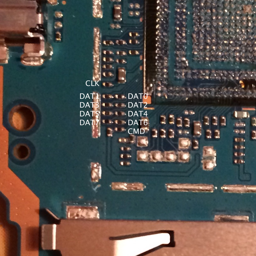
Next, I decided to remove all of the 150ohm resistors on the test points in order to get more solder surface area. Looking at the eMMC testpoints picture from last time, it’s important to note that the pad on the left of each resistor is the one coming from the eMMC while the pad on the right of each resistor is the one going to the SoC. The resistors themselves may be for current limiting or noise removal. Removing them is as simple as pointing at it with the hot air gun set to 380C for half a minute and then using tweezers to to remove them.
I also found it easier to solder wires directly to the SD card reader instead of to an microSD to SD card adapter. I first verified that the card reader still works and that my wires are not too long by soldering the other end of the wire directly to an old 128MB SD card. After verifying, I removed the wires from the SD card and attached them to the now exposed test points.
Unfortunately, it still didn’t work. The computer sees the SD card reader but believes no card is inserted. Again, there could be any number of problems including (still) bad soldering, Vdd not receiving power, or even read protection in the eMMC.
Attempt Three
Next I made another attempt to find Vdd. The problem is that my multimeter shows a short from Vdd to Vss. This means that Vdd is somehow shorted to ground either because I broke something with all the heat and bad soldering or because that is by design (which I don’t think is true because all documents I read say that you need to power Vdd for the eMMC controller to work). I thought maybe I can experiment by sending test voltages through various locations on the first logic board (the one with the chips removed) and see if I get a voltage drop in the Vdd pad. I used an old broken MP3 player as my voltage source (since it was just laying around and I didn’t want to buy a power supply, rip open any working cable/device, or solder to a battery). I attached the positive end to a pointed screwdriver and the negative end to the Vita’s ground. Then I attached one probe of my voltmeter to the same ground. Then with the screwdriver in one hand and the voltmeter probe in the other hand, I tried to send voltage through every location on the board. Unfortunately, the only response was sparks on capacitors here and there but no response in Vdd.
Back to the second Vita, I tried to attach the battery and charger and turned it on. At first, I got excited and saw a voltage drop on the eMMC’s decoupling capacitor (meaning there’s power going to the eMMC). However, after going back and reattaching the wires, I could no longer reproduce the result. In addition, the power light no longer responds to the power switch. I believe that I shorted something and the first time I powered it on, it destroyed some component; so the next time I attempted to power it on, it fails before even attempting to power the eMMC.
Regardless, I tried to reattach all the wires with better soldering on the assumption that my only problem is still the bad soldering (likely not true). Being the fourth or fifth time doing this, I am getting better at soldering these extremely tiny points. My trick was to first align the wire to the board and then using the tweezer, make a 90 degree bend on the end of the wire. This makes the end of the wire the same length as the original resistors. Then I quickly dip the end in solder, flux the board, and attach the wire to two pads instead of one. This makes a stronger connection. Even though I did a much better job and soldering the test points, I still could not get anything to show up on my computer.
Attempt Four
Now that I have experience in soldering tiny points, I made an attempt at soldering directly to the eMMC removed from the first Vita. However, after a quick test (nothing shows up on the computer), I didn’t look any farther because I believe that the eMMC must be part of a circuit of capacitors and resistors in order for it to work (and not break the chip). All documents I’ve read supports this.
I also made yet another attempt at resoldering to the board again and still no luck. At this point, I believe that either I still am not powering Vdd correctly, or I broke the eMMC at some point. I also suspect that perhaps my SD card reader does not support the Samsung eMMC or that it is not being initialized correctly.
What’s Next
I still haven’t given up. I will continue to try resoldering the points. I still want to find a way to surely power Vdd; I bought another Vita from eBay because I believe the second Vita is now broken. I also ordered a eMMC socket with the last of the usable donations, but it will take at least a month to arrive from China. There’s also the possibility that the eMMC does something unsupported by my SD card to USB adapter and I want to do some raw signal interaction with an Arduino. If you want live updates of progress as I’m working, join #vitadev on EFnet.
-

- Professional soldering and reflow station fresh out of the box.

-

- microSD to SD adapter torn apart and wires soldered in

-

- Shield removed on new board. Much easier this time with a reflow station.

-

- Another angle.

-

- Old logic board. The trace points with the resistors removed.

-

- Old board. Coupling capacitors next to the eMMC removed.

-

- Attempt 1: Wires soldered directly to resistors and to an adapter.

-

- Look at the horrible soldering job

-

- Attempt 2: Resistors removed. Vddf found and soldered to Vdd from SD reader.

-

- Wired directly to a USB SD card reader

-

- Contraption built to send test voltages to board.

-

- Attempt 3: Refluxed pads and tried again

-

- Better soldering job this time

-

- Attempt 4: Tried hooking wires up directly to eMMC and SD adapter

-

- Attempt 4: Also tried resoldering pads one more time

-

- Zoomed out

Keep up the work, you are our hope! Go gogogo!
Nice job! You work is great,man! You are the first man vita native Jack! The brazilian nation Sends A hug for you o/
Nice job! You work is great,man! You are the first man vita native hack! The brazilian nation Sends A hug for you o/
Do not give up friend! Much more many people are hoping for you! And hope for good news! You can!
Your work is really “High level”!!, You are the Hope in a time hackers became selfish… , The way you share every information you got, every step, even if you Fail. you retry <3. Your Name is already related to The "Ps Vita Hacking" Now.
Arabic forums send you Greating ! and you are realy famous there ! Greeting from your Fan from Morocco!
Wish you the Best :D :D
Keep up the good work, I’m cheering you along with the others! :D :D
you arE tHE BESt Bro’W
Don’t give up and continue your good job. I heard somewhere the PS Vita use a NetBSD operating system and not a Linux anymore like the PSP. Maybe you should try to mount it on a BSD operating system like freebsd or PC-BSD for the easy install. You could get more chance to mount the file system to be able to dump it. Sorry i am noobz with hardware if it something else.
I thought my D0 xbox job was hard, you’re winning by far. Keep it up bro!
http://akiba.geocities.jp/psp_devolution/
サポートされるデバイスの一覧は、今後追加されていく予定です。 M65KA256AF WAFER M65KA256AL TFBGA107 M65KA512AB LFBGA107 M65KC512AB WAFER M65KG256AB TFBGA149 M65KG256AF TFBGA149 M65KG512AB TFBGA149 NAND01G-M LFBGA137 NAND01G-N TFBGA149 NAND256-M TFBGA149 NAND512-M TFBGA107 NAND512-M TFBGA149 NAND04GW3C2A 512Mbx8 NAND08GW3C2A 1Gbx8 NAND01GR3B 128Mbx8 NAND01GR3B2B 128Mbx8 NAND01GW3B 128Mbx8 NAND01GW3B2B 128Mbx8 NAND02GW3B2C 256Mbx8 NAND04GW3B2B 512Mbx8 NAND08GW3B2A 1Gbx8 NAND01GW3A2B 128Mbx8 NAND128W3A 16Mbx8 NAND256R3A 32Mbx8 NAND256W3A 32Mbx8 NAND512R3A 64Mbx8 NAND512W3A 64Mbx8 K9F5608B0D 32Mbx8 K9F5608R0D 32Mbx8 K9F5608U0D 32Mbx8 K9F1208R0B 64Mbx8 K9F1208U0B 64Mbx8 K9F1208B0B 64Mbx8 K9K1G08R0B 128Mbx8 K9K1G08B0B 128Mbx8 K9K1G08U0B 128Mbx8 K9F1G08U0B 128Mbx8 K9F1G08R0A 128Mbx8 K9F1G08U0A 128Mbx8 K9K2G08R0A 256Mbx8 K9F2G08R0A 256Mbx8 K9F2G08U0A 256Mbx8 K9K2G08U1A 256Mbx8 K9K2G08U0A 256Mbx8 K9F2G08U0M 256Mbx8 K9F4G08U0A 512Mbx8 K9K4G08U1M 512Mbx8 K9K4G08U0M 512Mbx8 K9F4G08U0M 512Mbx8 K9K8G08U1A 1Gbx8 K9K8G08U0A 1Gbx8 K9K8G08U1M 1Gbx8 K9K8G08U0M 1Gbx8 K9W8G08U1M 1Gbx8 K9WAG08U1A 2Gbx8 K9WAG08U1M 2Gbx8 K9NBG08U5A 4Gbx8 K9NBG08U5M 4Gbx8 例) PSP用であれば、 K9F2G08U0A 256Mbx8を選択してください
Hey Yifan do you live in Houston near that tenis court? nice place!
Which tennis court?
well i only see one nearby. coordinates 29.747031, -95.786781
No, I’m hundreds of miles away from there.
Can you give more updates on the process Yifan Lu, will the cartridge games be able to play on it after the hack or you are not able to answer that? Keep up the good work!